The Monarch Flies Into The Night
by William J. Orvis, LUNAR #309
After last fall's night launch, I was looking for something new and different to use in a night flying rocket. I had a couple of ideas and was looking through my electronics catalogs to see what was available. That's when I saw it; a miniature fluorescent black light. The light was one eighth of an inch in diameter and four inches long. I just knew there had to be a really cool way to use a black light on a night flying rocket, so I bought one plus the special inverter need to power it.
I didn't have a specific rocket design in mind when I ordered the light. In fact, I was thinking about a lot of different designs that could use the lights. White rockets where the whole rocket glows, black rockets where only the outlines of the fins and port holes glow; multicolored rockets that glow all over (I even considered a tie-dyed rocket but I think I will leave that to my daughter.) All of these designs were good looking and you may see some of them over the next few years but I wanted something really different to build this time.
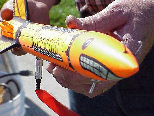
The Monarch; a fluorescent painted rocket lighted with a miniture black light. (JPEG 51KB)
(photo by David Miller)
I started thinking about butterflies as a model for a rocket design, I mean, they are really colorful and I have never seen a butterfly rocket before but the wings of a butterfly are just the wrong shape to use for rocket fins. Then I spotted a ceramic Monarch butterfly sculpture in my daughter's room. This one had an elf riding on its back and had the front wings swept back in flight position. On seeing this, I knew I had my design so I swiped the ceramic butterfly and designed the Monarch rocket using the sculpture as my model (For some reason, my daughter kept swiping the sculpture back but I know where she keeps it.)
The Light
The miniature fluorescent lights I used were designed to supply the back lighting for the flat panel displays used in laptop computers and personal digital assistants. The lights are one eighth of an inch in diameter and from 2 to 8 inches long (fig. 2). The lights are available in white, ultraviolet (black light), and in several colors (green, red). They need a special inverter (fig. 3) to make the 600 to 800 Volts needed to make the lights work. The inverters run on either 5 or 12 Volts. They are cold cathode fluorescent lights, that is, there are no heaters at the ends of the tubes like their larger cousins you find in most homes. They require a high voltage pulse of about 800 volts to start and then about 500 volts to sustain their operation. Both the starting and sustaining power is supplied automatically by the inverters. Note that when designing with these inverters be careful with the high voltage leads. If you short them against any other circuit, it will kill it. If you touch them, there is not much current available so it is unlikely to do you any permanent damage but the 500 volts should sting.
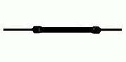
Miniature, cold cathode, fluorescent lights (1/8" dia.,
2 to 8" long).
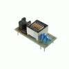
The 12V inverter needed to generate the 500 to 800 volts needed by the lights.
I ordered a white light-inverter combination (All Electronics #BFA-4250 $12.75) which consists of a 9.8 inch white light and a TDK #D160 inverter, and a four inch long black light (All Electronics #UV-3100, $10.75). The inverter was supposed to require 12 volts to operate but when they arrived, I decided to try a 9V battery just to see what would happen. I was prepared to chop up a couple of 9V batteries and make a 12V battery out of the pieces but the lights worked just fine on the 9V battery.
I inserted an ammeter in the circuit to see how much current the inverter used. It was specified at 235 mA at 12 volts and was using 180 mA at 9volts. That is a little stiff for a 9V transistor radio battery as they are designed to put out about 10 mA. While I was pushing the battery at about 20 times its normal rate, it seemed to be holding up fine. If it can keep up that drain rate, I should be able to get about 2 hours of run time on a single battery (9V batteries have an energy rating of about 550 mAh.) So far, I have operated it about 15 minutes on a single battery and have had no problems.
The only problem I have had with this light is that it occasionally does not turn on when the lamp is cold. Cycling the power on and off a couple of times usually gets the lamp to light. When it finally turns on once, the internal arc heats the lamp a little and it turns on easily after that.
One of the biggest problems with lighted rockets is running out of battery power while you are showing it off to your friends and while it is sitting on the pad waiting its turn to launch. To reduce the drain on the internal battery and to be able to use a fresh battery to get the lamp started when it is cold, I wired a miniature phone jack as both an on-off switch and an external power receptacle. When an unwired phone plug is inserted in the jack, the light is turned off. When the special jack with attached battery is inserted, the light operates off of the external battery instead of the internal one. I can leave the lights on while the rocket sits on the pad and simply run up (with the LCO's permission) and pull out the external power plug to switch to internal power for the launch. I plan to use this design on all my future lighted rockets.
Wiring diagram for the inverter with the external power and on-off plugs. (GIF 4KB)
The miniature fluorescent light and inverter I used are available from All Electronics (http://www.allcorp.com/index.html). Parts are also available from Jameco Electronics (http://www.jameco.com). The lights cost $8 to $12 each and the inverters are about $12 each.
Designing the Monarch
To design the Monarch rocket I had to consider the shape of the butterfly wings, the mounting of the fluorescent light, inverter and battery, and the stability of the rocket. In addition, I designed in a second light in the nose just in case the fluorescent light failed or broke. I had the basic shape of the fins from the ceramic sculpture. Stability was not a problem because the butterfly wing fins are huge compared to most rocket fins. The weight of the light was negligible (2 gm) and the battery and inverter only weighed about an ounce each so any design that put the inverter and battery ahead of the fins would not affect the stability.
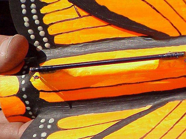
Close up of the miniature fluorescent tube held above the rocket on a standoff. (JPEG 61KB)
(photo by David Miller)
The main difficulty with designing a rocket to use the fluorescent lights is that in order to light up the outside of the rocket you must mount the light on standoffs that hold it out over the part of the rocket you want to light. I accomplished this using a U shaped piece of balsa with the light glued (epoxy) across the open end (fig. 5). The U shaped balsa standoff was made with two pieces of balsa sheet stock glued together with the grain of one sheet perpendicular to the grain in the other sheet for strength. I filled and smoothed the standoff using body putty.
Internal design of the Monarch. (GIF 9KB)
The inverter is a PC board that is 1.5 by 2.5 inches in size. It easily fits in a BT-60 body tube along with a 9V battery. To divert the ejection charge around the power inverter and battery, I cut the BT-60 body tube into two pieces and reconnected them with a tube coupler. The lower piece of tube has the fins, engine mount, light, inverter and battery. The upper tube has the body tube coupler, parachute and nose cone. I placed a bulkhead about 1 inch above the engine mount and ran an 8" piece of BT-20 tube through the bulkhead along the inside the BT-60 tube to a point just passed where the upper edge of the tubing coupler will be when the two tubes are assembled. I placed a second bulkhead on the top edge of the tubing coupler with a hole for the BT-20 tube. The battery and inverter go in the space between the BT-20 and BT-60 tubes The upper tube with the body tube coupler is slid onto the lower tube with the BT-20 tube protruding through the hole in the bulkhead. Secure the tubing coupler to the lower tube with a small screw. The ejection charge gases are diverted through the BT-20 tube into the upper part of the BT-60 tube to pop the nose cone and eject the parachutes.
Since I have only one black light, I can only illuminate two of the three fins. For the two that are illuminated, I made the fins with two pieces of balsa, exactly mimicking the wings of a butterfly. The third fin is a single piece of balsa with the two wings painted on it. From a short distance away, the two layer fins are almost indistinguishable from the single layer fins so if I were to do this again, I would probably paint the wings on all three fins.
The whole rocket was painted with fluorescent orange and yellow (Day-Glo) paint After the fluorescent paint was completely dry, I drew in the black lines first lightly with a pencil and then with a black Sharpie pen. I then filled in the larger areas by hand with flat black paint and a brush. When the black paint was completely dry, I painted in the white spots on the wings, teeth and eyes using phosphorescent paint. The phosphorescent paint glows nicely under the black light and continues glowing after the light is turned off.
Flying the Monarch
The total weight of the rocket with an engine is 11 ounces, which is too much for a C engine but well within the 14 oz max for a D engine. I flew the Monarch with a D12-3, which was just about right for its weight and size.
The Monarch on the pad, ready to go. (JPEG 9KB)
(photo by David Miller)
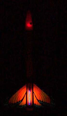
Sitting on the launch pad the rocket fulfilled its name and appeared to be a huge Monarch butterfly ready to fly. As it flew, the black light only illuminated the wings and that part of the body tube adjacent to the wings, effectively hiding the nose of the rocket. The result was a large Monarch butterfly flying through the sky with a bit of fire on its tail.
It sure feels great when a good design comes together.
Post Flight Analysis
The fluorescent lighting worked flawlessly throughout the flight. The only casualty was the safety light in the nose cone. The safety light was there in case the fluorescent light broke and consisted of two AAA batteries, a large, red LED, and a switch. The whole assembly was in the nosecone, attached by only the switch, which protrudes through the side of the nosecone (you can see it at the bottom of the nosecone in fig. 1). Apparently, the shock at ejection caused the batteries to place too much stress on the switch, tearing its back off. This problem has since been fixed with a new switch and with the batteries secured to the nose cone with silicon rubber sealer instead of hanging on the switch.
Copyright © 1999 by LUNAR, All rights reserved.
Information date: July 25, 1999 lk