
By William J. Orvis, LUNAR#309
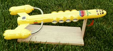
The Galactic Apple, which I have been showing off at launches for the last year in various stages of completion, finally flew at the April night launch. Those of you who have seen it, a big yellow thing with giant portholes and Apple stickers, probably wondered just what it was. Well, here it is, it has flown once and is ready for more.
In case you are wondering why I built such a strange looking thing, I had a nine inch long, 1/8 inch diameter, white fluorescent light that needed a holder and the Galactic Apple is it.
I have always wanted to build a rocket with portholes that you could look into and see things inside. As such a rocket needs a lot of internal lighting to look good so this seemed like an ideal holder for the long fluorescent. While designing it, my mental image was one of a ‘20s style fictional rocket with its sea ship like portholes and multi-paned windows.
I’m not sure what the pod on the end of each fin represents; fuel tank, antimatter pod, beer keg, but in the model, they have a real function. One pod contains the recovery system and the other is a vent for part of the ejection charge so the charge does not blow the rocket apart.
A lot of people have wondered about the name and the Apple stickers on the outside. They are the result of a brainstorming session among my kids and I. I was originally going to use something like United or TWA. Then we started thinking about what company would be in the transportation business a hundred years from now. Names like Ford and Microsoft came to mind. Finally, the brainstorm, this was going to be galactic touring in style for the rest of us and the Galactic Apple was born. Besides, Macs outnumber PCs at my house and I had a handful of Apple stickers just waiting for a good use. I guess I should have painted it in candy colors, but I already had the yellow.
As I stated above, this rocket was designed as a holder for the fluorescent light. The light itself is about 9 inches long, so that defined the length of the passenger compartment. As the passenger compartment completely filled the center section of the rocket there was no way to vent the ejection charge around it to create a standard, nose cone ejecting recovery system. The result was that the rocket had to be designed to keep the ejection charge and recovery system in the aft section. The electronics and batteries went into the front.
The rocket separates into three parts. The rear section separates just behind the passenger cabin and is secured with 5 screws. The rear section contains Engineering with its one porthole, the engine holder, fins, pods, and recovery system. The separation is needed here to be able to feed the wires into Engineering to power the lights and to attach the high voltage power lead to the aft end of the fluorescent light.
The main cabin has two, thick, pasteboard bulkheads, one at each end. The rear one is to keep the ejection charge out of the main cabin and the forward one is to keep the batteries out. The main cabin has a floor for attachment of the chairs and people. The forward compartment of the main cabin contains the 12V battery and the high voltage inverter for the fluorescent light.
The forward section of the rocket consists of the pilot’s cabin in the nosecone. The forward section also contains lighting for the pilot’s cabin and a headphone jack that serves as an on/off switch and as an external power connector. The floor of the pilot’s cabin is centered in the nosecone. The pilots themselves are only modeled from the waist up. The nosecone is secured with tape when the rocket is launched.
My original plan was to fly it with a E15-4 engine so I designed in a 24 mm engine mount. As construction neared completion, the weight moved passed 20 ounces and it quickly became apparent that an E just was not going to get this thing off the ground. I had to remove the 24 mm mount and replace it with a 29mm engine mount and fly it with an F.
The rocket was built in three sections: Engineering, the passenger cabin, and the pilots cabin. These three sections were then assembled into the completed rocket.
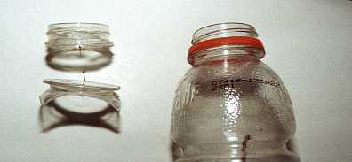
The first problem in constructing this rocket was to make the portholes. They needed to be a clean design and stick out a little. My mental image was of an old style ships porthole with rivets all around the outside. I wandered around the hardware store, looked through the trash at home, and checked my junk box for anything round and porthole like. I was not having much luck and was considering just painting them on the outside of the body tube. I sat back with a Gator Aid to think about it and a porthole was staring me in the face. The mouth of the Gator Aid bottle is much wider than a normal soda bottle. In fact, it is just the right size to make a large porthole on a BT-80 body tube.
A case of Gator Aid later and I had my portholes.
I made the portholes by cutting off the Gator Aid bottle at the base of the threads and again a couple of inches down into the bottle. I happen to have a drum sander about the same size as a BT-80 body tube so I sanded the back of the porthole to fit the curve of the body tube. The resulting piece is on the bottom left of this picture. On the top left are the threads that were cut from a bottle like the one on the right.
I marked the centers of the portholes on the BT-80 body tube and scribed the holes using a compass. Scribing on a cylinder with a compass makes an oval shaped hole but that matched well with the shape of the portholes. I cut out the holes in the body tube and then glued a Gator Aid porthole over each one using epoxy. When the epoxy was hard, I used body putty and glazing to fill in around the portholes and make a smooth transition to the body tube.
The last step in making the portholes is to add the windows. This is actually the last step when building the rocket as you need the portholes open to get things inside of the rocket. The windows are made with standard, clear packaging tape. This stuff looks like heavy, two inch wide scotch tape. Pull about five inches off the roll in a single pull. If you don’t do this in a single pull, there will be a line across the tape in the adhesive that you don’t want in your window. For the same reason, do not touch the center section of the tape with your fingers or anything else. Pick the clearest section of the tape, stretch it over the porthole, and trim the extra tape flush with the outer edge of the porthole. There is adhesive on the inside of the windows but as long as your rocket is clean on the inside, the windows will stay clean. If they do get dirty, it’s easy peal off the tape and put on a new, clean piece.
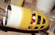
Engineering is made from an 8 inch section of BT-80 tube with a 29 mm engine mount. The fins are made with ironwood. They feed through slots in the BT-80 tube and are epoxied directly to the engine tube. The hole for the engineer’s porthole makes it really easy to epoxy the fins to the engine tube. The pods on the other end of the fins are made from Mountain Dew bottles with the threaded end cut off. The fins fit through slots in the Mountain Dew bottles and are epoxied on both the inside and outside of the bottles.
One of the two Mountain Dew bottles contains the two parachute recovery system. The bottle is cut off about an inch and a half up from the bottom and then the piece is reconnected with a tubing coupler. The shock cord is attached with epoxy to the root of the fin on the inside of the bottle, not to the bottle itself. The other end of the shock cord attaches to the cut off bottom of the bottle with the parachutes attached to a loop in the cord a few inches back from the bottom.
The tops of the two bottles are attached to the BT-80 tube with two curved pipes. The function of these pipes is to conduct the ejection charge gases from inside the body tube to the pods. I was originally going to use clear vinyl tube but while looking around the hardware store, I came across a metal braid covered washing machine hose and knew I had found my pipes. The hose is inserted into the neck of a Mountain Dew bottle and then the neck is filled with hot glue. Be careful with the hot glue. If you spill it down into the Mountain Dew bottle, the hot glue distorts the thin sides of the bottle. I dressed up the top of the bottle with a paper washer cut to just fit the pipe and the top of the bottle. The other end of the pipe is epoxied on the inside of the BT-80 body tube.
The points where the two pieces of pipe connect to the BT-80 tube are within a quarter inch of the end of the tube so they interfere with the tubing coupler that attaches Engineering to the passenger cabin. The tubing coupler is glued into the bottom of the passenger cabin and is notched on both sides to fit around the two pipes. These notches weaken the tubing coupler significantly. If I were to do this again, I would glue it into Engineering instead of the passenger cabin. When Engineering is joined to the passenger cabin, it is secured with 5 small screws.
I was concerned that the small hose would not let enough of the ejection charge pass into the pod to eject the parachute. I did a bench test (I duct taped the rocket to my vice) of the ejection system with an A engine, figuring that if an A could deploy the parachute an F would have no problem. However, when I did the test, in addition to filling my garage with smoke, I nearly had a separation between Engineering and the passenger cabin. The parachute and end cap went clear across the room and bounced off the wall.
After this test, I knew I had more than enough pressure to pop a parachute. In fact, I had too much. To lower the pressure a little, I removed the plug I had put in the pipe to the second pod and drilled holes in the bottom of the pod to let some of the ejection charge gas escape. I also added a couple more screws to the coupler. I was still concerned that I might blow the rocket apart with an F engine so I tested it again with a D engine (I’m not quite ready to waste an F engine on a bench test). I filled the garage with smoke again, there was some leakage around the tubing coupler but it did not separate and the end cap and parachute bounced off the wall like before.
I put one porthole in the side of Engineering that shows the engine mount and the engineer keeping things running smoothly. I decorated the inside with clippings from ads in the newspaper and from catalogs. The picture of the Dreamcast computer game machine looks like a big circular door with hinges and a locking mechanism so I glued one on the side of the engine tube. I was very pleased with the look, as it appeared to be a secure door to the main reaction chamber but every kid who has looked in there wanted to know why I put a picture of a game machine in there. Maybe that’s a comment on how most engineers view their toys.
In this picture, you can see the engine mount in the porthole with the engineer looking on. Three of the five screws that secure Engineering to the passenger cabin can be seen on the right. The pod at the top contains the parachutes. You can just see the cut at the bottom edge of the fin where the bottom of the pod separates from the top.
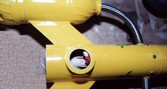
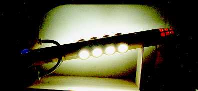
I put two blue LEDs in the engine compartment to give it a nice blue glow in flight (Cerenkov radiation???). It has also been suggested that the engineer should have a match in hand to help get the engine started. (Some suggestions I ignore.)
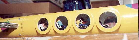
The passenger cabin is a 17 inch piece of BT-80 tube. It has four portholes on each side and heavy pasteboard bulkheads at each end of the passenger area. The one at the bottom is well epoxied in place, as it must keep the ejection charge out of the passenger area, which would really dirty things up. The upper one is also epoxied in place, as it must keep the batteries and electronics out of the passenger area. The upper one is not glued in place until nearly the last step as the inside of the passenger area is painted through that end. Each of the bulkheads has a 1 inch diameter engine block glued at its center and painted to look like a circular door.
Along the bottom of the passenger compartment is a floor made from foam board. Foam board is that ¼ inch thick poster board that has paper on both sides and a foam center. It is easy to shape to fit snugly in the bottom of the body tube. The electric wires for the fluorescent light and the LEDs in Engineering pass through the small space beneath this floor. I put in a few extra wires just in case one broke during construction.
At this point, the interior of the passenger cabin is painted flat white to reflect as much light as possible out the portholes. When the paint is dry, I installed the fluorescent light and glued it in place with a couple of dabs of Shoe Goo (wonderful stuff for modeling). I installed the front bulkhead and decorated both bulkheads with pictures of computer screens and door controls clipped from some old catalogs. I think the door control was a cell phone with the antenna clipped off.
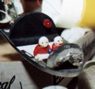
The next step was to make the chairs and the people. The chairs have a foamboard base with two pieces of stiff pasteboard glued on them to make a seat and back. I maneuvered these chairs through the portholes and glued them to the floor. The people are made with Sculpey clay. Sculpey clay is actually a plastic that hardens to the consistency of hard rubber when you put it in the oven for a few minutes. I sculpted the people to fit in the chairs and then baked them to make the clay harden. After they cooled, I painted on their clothes, hair, etc. I thought they came out pretty good, but my kids think they belong on Planet of the Apes (I never claimed to be a sculptor).
When the paint was dry, I maneuvered them into the chairs through the portholes using some forceps borrowed from my wife’s black bag (veterinarians have such nice tools for modeling, now if I can just get the glue and paint off). I glued them in place on the chairs and elsewhere in the passenger cabin. You can see some of them siting and another standing in the back of this picture.
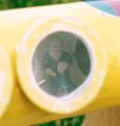
In addition to normal people, I included babies, a princess,
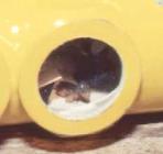
and a Dachshund named Bubba. (The real Bubba lives here at home, while I have often wanted to fly him to the moon, this is about as close as he is going to get.)
The control room is made from a blunt BT-80 nosecone like that used on the Estes FatBoy. Using foamboard, I made a floor at the exact center of the nosecone. I then made two half circle bulkheads of foamboard to make a rear wall and a front wall/control panel for the control room. The two pilots in the control room are only half people. That is, they are only modeled from the waste up. The control panel at the front has three flashing LEDs and is decorated with clippings from magazines and catalogs. I clipped out enough pictures of knobs and levers and screens to cover the front panel and to wrap around the pilots. The back wall of the control room has a jumbo red LED in it to light the area.
The hardest part of the nosecone is cutting out the windows. Mark them carefully on the plastic then cut them out with a hobby knife. Don’t push hard but go over the same line again and again until you cut through the plastic. If you push too hard, the thin frames around the windows break. I managed to crack them in a couple of places and had to put an epoxy layer on the inside to strengthen the remaining grid.
When I painted the nosecone, I put tape on the inside of the windows to keep the paint out of the interior of the nosecone but to let it color the edges of the cut windows.
When the painting was done, I decided to not put windows in the frames. They were designed so that I could put tape over the outside like the portholes but there is no good way to trim the edges of the tape without scratching the nosecone. I don’t think the lack of windows adds any significant drag to this rocket.
The 1/8 by 9 inch white cold cathode fluorescent light needs 600 to 800 volts of high frequency power to operate. Luckily, there are commercially made inverters designed just for these lights.
The inverters are designed for 12 volts and will operate at 9 volts, but the lights are very difficult to start at 9 volts, especially on a cold April evening. I built a power source by cutting up two 9V batteries and soldering together 8 of the mini cells found inside to make a 12 volt battery.
The inverter uses about 200 ma and the LEDs use another 50 so you are pushing this cell well beyond its maximum discharge rate. Most 9V cells are rated at about 500 mah so at most, you should get 2 hours out of the system. In reality, you get about 15 minutes at normal brightness and then the light dims significantly. I am pushing these cells so hard that the chemistry does not have a chance to equalize. A nicad battery might work better as it can handle a higher power drain rate.
The following figure shows the wiring diagram used in this rocket.
All of the lights operate off of the 12 volt battery. The power first feeds into the headphone jack on the bottom of the nosecone. The jack serves the dual purpose of an on/off switch and an external power connector. Inserting a headphone plug opens the switch in the jack and turns off the power. Inserting a headphone plug with a 12 volt battery attached applies that power to the lighting circuit instead of the internal battery. The external battery pack is made of two lantern batteries taped together. This is especially important while the rocket is sitting on the pad, waiting to go. Many times I have seen peoples lights run out of power waiting to be launched. With an external power connector, I can run on the larger batteries until just before it flies and then run in and pull the connector to go on internal power.
After the headphone jack, the power goes to the inverter and to the LEDs.. The blue LEDs operate at about 5 volts each, so two of them in series with a 120 ohm ballast resistor works quite well on 12 volts. The one jumbo red LED operates at 2.2 volts and needs a larger (320 ohm) resistor to keep the current down. The three flashing LEDs operate on the 12 V and can share a 750 ohm ballast resistor. We want to keep the current through the LEDs in the range of 10 to 40 ma. Any more current than that damages the LEDs.
When assembling the electronics, I put the battery and the inverter in the front compartment of the passenger cabin. The pins on the inverter make really nice binding points for all the connections. One of the outputs of the inverter connects to the upper end of the fluorescent light and the other goes under the floor to the lower end of the light. Power for the two blue LEDs in Engineering is routed under the floor of the passenger cabin, through the back of the engine mount and into Engineering. The only problems I have with this is that the ejection charge keeps breaking the connections to the blue LEDs.
The red LED and the flashing LEDs are powered from the same terminals on the inverter. The resistors are attached at the back of the foamboard panels.
Make sure the holes through the rear bulkhead of the passenger section and the forward centering ring of the engine section are well plugged with hot glue or Shoe Goo. If you don’t, the ejection charge will leak into the compartment and muck things up.
When everything is working, install the tape windows over the portholes and you are done.
At the April night launch the Galactic Apple finally got to fly. I took it to the fall night launch but it wasn’t ready to fly then. It didn’t have people yet and I had to change the engine mount from 24 to 29 mm. Over the winter, I removed the 24 mm engine mount, installed a 29mm one, made the people, and installed them. By April, it was ready and raring to go.
I displayed it in the afternoon, waiting for it to get dark. Some of my “friends” were taking bets as to whether all the people inside would end up in a little pile at the back of the passenger cabin after the launch. Maybe they didn’t realize that my people use epoxy instead of seatbelts. A couple of kids came by and asked why I put a game machine in Engineering. Don’t they know a door when they see one???
As it got dark, I installed an F25-4W engine and loaded the parachute in the fin pod. I installed an IgniterMan igniter (no copperheads for this machine) and checked out the lights. I had to fly it off the high power pads (such is life with an F engine). When it was my turn, I switched to internal power and told the LCO to make it go. Away it went, flying true and straight. Well, how would you expect it to fly with the drag of a soda bottle on the end of each fin. Then, just at engine burnout, it gave what most people described as a little wiggle. None of us have been able to figure out just what caused that wiggle. There was some speculation that some last bit of fuel might have somehow come out crooked to give it a little kick. Maybe it was just the wind.
It arced on up and ejected the parachute right on time and floated down to the ground, hanging by one fin. When I picked it up, the first thing I noticed was that the blue lights in Engineering were out. I shined a light into the window and found that it was coated with soot. In fact everything was sooty, including the engineer (Rats! Lost another engineer). On closer examination, I found that I had not done a good enough job of plugging the tiny hole between Engineering and the back of the engine. When the ejection charge fired, some of the ejection gas leaked through that tiny hole into Engineering. Actually, a lot of gas leaked in there, turning everything slightly brown in color and dirtying up the window. The ejection charge had also broken one of the wires to Engineering’s lights, which is why they were out.
Additionally, there was a small split in the body tube, just back from the nosecone. It appears that because the rocket was hanging from one fin, it was at a slight angle when it hit the ground, which caused one side of the body tube to get most of the stress and split. I am going to have to add a larger parachute and possibly some kind of a sling to make it come down sideways.
Also, only one person was piled up at the back of the passenger compartment but he was still in his seat. A little more epoxy put him and his chair back where they belonged.
After completing this project, I have the following words of wisdom concerning designing strange looking rockets with lights.
· Rocket designs always get heavier than the engine you designed in can handle (especially when you fill the rocket with batteries, lights, electronics, and clay people).
· Rear ejection rockets don’t come down any slower than front ejection ones.
· Ejection charge soot can leak through the smallest of holes.
· Friends will bet on almost anything.
· Battery power always runs out just as the LCO is ready to fly your rocket.
Enjoy