 LUNAR’clips
2004
Volume 11, Number 1
LUNAR’clips
2004
Volume 11, Number 1
LUNAR’clips
2004
Volume 11, Number 1
Livermore Unit of the National Association of Rocketry January/February 2004
Copyright © 2004 by LUNAR, All rights reserved.
By By William Orvis, LUNAR#301
Last year, while visiting my parents I was digging around in a closet and found my grandfather's Kodak Stereo Camera (see Fig. 1). Along with it was a box of stereo slides but the viewer was missing. A lot of the slides were of my cousin and I when we were about 5 years old. I sort of remember my grandfather using the camera but not much more. I pulled out the camera and everything seemed to be working. This is an old, manual camera built way before any of the current automatic models. As it was all manual, there was not much that could go wrong, no batteries to leak or circuits to age. I wondered if it would still work, as this seemed like a great camera for taking pictures of rockets.
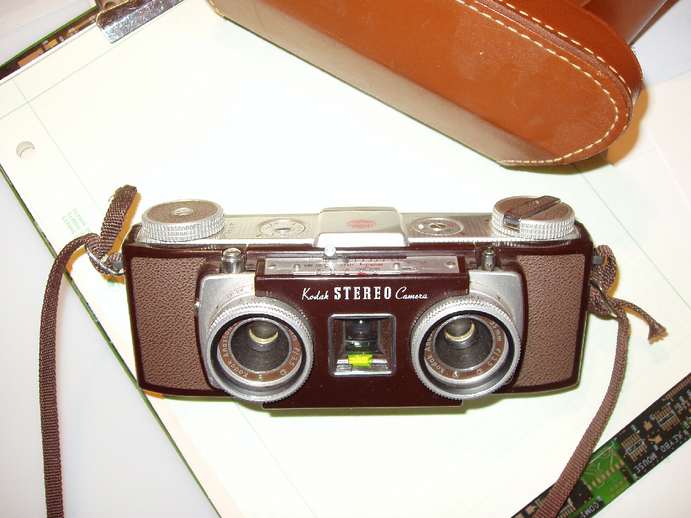
Figure 1. A Kodak Stereo camera
I took the camera home and started looking around for film and slide mounts. The Kodak Stereo Camera shoots a half sized slide known as "Realist Format" through each of its two wide angle lenses. These two slides are then combined in a slide mount that can be viewed with a drop-in viewer. A "Realist Format" slide mount is 4 inches wide and 1 5/8 inches tall. It holds two 35 mm half wide film chips in two 7/8 by 15/16 windows. The film originally came with developing and slide mounting included in the price. You just mailed the film back to Kodak and received back the mounted slides. As you might expect, the 3D film is no longer available but it was normal 35 mm film so it seemed that I should be able to make something work.
My first stop was to contact a friend of mine, Jack Toeppen (http://home.comcast.net/~toeppen/), who is really into 3D photography. He looks at 3D photography the same way we look at rockets and is responsible for some pretty incredible shots. In fact, if you have ever bought a CD of 3D images, he is probably the photographer. I want to thank Jack for getting me started.
Jack pointed me to some websites where 3D enthusiasts sell equipment to other enthusiasts, including, film mounts, instructions, mounting kits, cameras, and other equipment. At one website I found copies of camera manuals available and immediately ordered one for my camera. From another site, I bought heat-sealed slide mounts, a film cutter, and instructions on how to cut and mount 3D slides.
The original viewer that came with the camera was missing. It was a battery powered device that backlit the slides and that you viewed like using binoculars. I found one available but it was over $100. I didn't really want to spend that much to try out an old camera. With a little more searching, I found a simple plastic viewer (Fig. 2) for $2.00. This viewer works very well considering the price. It actually is more useful than the expensive one as I can afford a bunch of them. With multiple viewers, several people can look at some slides at the same time instead of having to wait while the viewer is passed around. Additionally, I can give away a slide and include a viewer without worrying about the cost. This is important to me as I tend to give away a lot of my photos.

Figure 2. An inexpensive slide viewer.
According to the manual, I can use normal 35 mm slide film in the camera without a problem. I just have to adjust for the number of slide pairs I can make on a roll. I found some ASA 200 color slide film at the store (it was the only choice I had) and loaded it into the camera. This is where the first problem appeared. The original camera is setup for ASA 64 film and had no indicators for faster film. Luckily, if you tear open the film box and turn it inside out you will find old fashioned exposure instructions. These showed me the speed and f-stop settings to use for different lighting conditions.
Armed with a camera loaded with film, I went to the June, 2003 LUNAR launch and began shooting pictures of people and rockets. The camera has two, wide angle lenses with a large depth of field. Lenses of this type are needed on a 3D camera because you want things at different distances from the camera to all be in focus at the same time (the depth of field). Actually, having faster film makes this work even better as the higher the f-stop setting, the deeper the depth of field. For example, with an object focused at 10 feet and a setting of f8, the depth of field ranges from 5 feet to infinity. Which means that with that setting, objects from 5 feet to infinity are all in focus at the same time.
A camera of this type shoots two images with a separation of 2 3/4 inches, which is comparable to that of human eyes. As such, depth perception using parallax only works out to about 15 feet. Beyond that distance, your eyes use visual queues to see depth. Because of this, a 3D camera of this type works best for subjects within 5 to 10 feet of the camera. It works for more distant objects but the 3D effect is not as dramatic.
After shooting a roll of film, you need to get it developed but not cut or mounted. If you try this, be sure to mark on the development envelope "Develop Only, Do Not Cut". The film comes back in a single piece, in a plastic cover, and rolled into a small tube. As soon as you get it home, remove it from the tube and hang it up or lay it on a flat table to get the curl out of it.
The next step is cutting and mounting. The film comes in one long piece and so the individual film chips have to be cut apart. To do this, you need a light table, gloves, tweezers, and a film cutter or sharp scissors. You can probably do this without a light table but it is much easier with one. You need gloves so you don't get oils from your hands on the film. I used vinyl examination gloves (one of the benefits of being married to a veterinarian) which you can get at the hardware store these days. Cotton gloves are supposed to work better as they keep the film clean and breath so your hands don't get all sweaty but I have not tried them.
Because the lenses of the camera are separated by 2 3/4 inches, the images on the film are not side by side but are spaced four images apart. To make this work, the film winder on the camera is designed to move by different amounts depending on which image you are taking. For the first three shots, the winder moves the film one image width to the right per shot. For the fourth shot, the images for the right lens are bumping up against the images taken with the left one. If you were to move a single image width, your right lens would shoot an image on top of the first image shot with the left lens so the winder moves the film four image widths right to the next unused patch of film. It then moves a single image width for the next three shots and so on. The resulting images on the film are upside down because of the way cameras work so if you rotate the film until the images are right side up, they will be in the following order with L and R signifying the left and right image for each shot.
1R 2R 3R 1L 2L 3L 4R 5R 6R 4L 5L 6L 7R 8R 9R 7L 8L 9L …..
Look closely at the sequence. The right images are on the left and the left ones are on the right. To help you out, the Kodak camera puts a small triangle at the top of the left images and two at the top of the right ones. This makes it easier to figure things out if you mix up your images. If you have multiple images of the same subject, be really careful that you don't mix them up while cutting the film. It is really easy to mix them up as static makes the film chips stick to everything.
Cut and mount a single shot at a time until you get the feel of it. Using the film cutter or some sharp scissors, cut out the film chips for the shot you want to mount (Fig. 3).

Figure 3. Cutting the film strips with a film cutter.
The mounts are die cut cardboard with indentations to center the film chips (Fig. 4). The mounts I chose seal with a hot iron. Also available are self-sealing mounts and taped mounts. The heat-sealed mounts create a relatively permanent slide and are a lot less expensive than the self-stick mounts. The mounts are placed as shown in the figure. The film chips go in the bottom two windows of the slide mount and the top part is folded over and sealed. The film chips are placed in the bottom two windows so that after sealing, the slide can be flipped over and viewed correctly. That is, on the open slide mount, the film chips are placed right side up with the image taken with the left camera lens on the right and the image taken with the right lens on the left. The film is placed there with the shiny side down and the curl up.

Figure 4. A die cut Realist format film mount.
Secure the filmstrips in place with silver mylar tape or an adhesive backed paper strip as shown in Figure 5. Masking tape and scotch tape do not work well. Silver mylar tape works the best but the pre-cut adhesive strips are the easiest to use. Fold over the mount and seal it with a hot iron. Do not iron over the film but only on the paper around it. The images can now be viewed in the viewer. If the image looks odd and your eyes try to cross while looking at it, you have likely reversed the left and right images or have flipped the film over and are viewing it backwards.

Figure 5. A film mount with the film chips in place.
This completes the mounting of the 3D images but in this form, they can only be viewed with a viewer. To view them on a web page or in this printed journal, they need to be digitized. To do so requires a slide scanner or a special flat bed scanner with a transparency scanning attachment. The attachment is needed to light the slides from behind. I use the Microtek Scanmaker 6000, which comes with a transparency scanning attachment (Fig. 6). The slide is placed on the scanner and the transparency attachment is placed on top of the slide. The scanner scans the whole slide including both images at one time. These images are too far apart for you to fuse without some kind of a viewer so I use some image editing software to put the two images side by side on a black background as shown in figure 7.

Figure 6. The Microtek ScanMaker 6000 scanner with the transparency scanning attachment.

Figure 7. A completed, side by side, 3D image.
Now that you have an image to look at you need to fuse the two images into a single image in order to view the 3D effect. What you need to do is to relax your eyes while looking at the two images so that your right eye looks at the right image and the left one looks at the left image. As your eyes relax and look straight forward, the two images will appear to slide over each other until they fuse and you see the 3D image. It takes some practice but you will know it when it works. Figure 8 shows some more images taken at the EBRC Airshow. As you can see, taking a picture with a long pointy thing pointed at the 3D camera gives very interesting results. More of these images are available on the LUNAR website at,


Figure 8. 3D images from the EBRC Airshow (My rockets, Jack Hagerty, Joe Pettinicchi, Greg Wong).
Some people are more comfortable viewing 3D images using the cross eye technique. Reverse the images so that the left image is on the right and the right image on the left. View the images with your eyes crossed so that the right eye looks at the image on the left and so forth.
This paper has shown how to make 3D images of rockets and other subjects using some very old 3D technology that works quite well. More modern technology is available including a camera that shoots two images on a single frame of film. The images are printed like any other photos and can be viewed with a simple viewer. More advanced techniques involve attaching two digital cameras on a board with several feet separation. You then use a trigger cable connected to both cameras that triggers them both at the same time. The farther apart the cameras, the more distant an object may be and still give the 3D effects. Descriptions of some of these effects are available on the web references listed below.
Jack Toeppen's web pages: (http://home.comcast.net/~toeppen/)
Rocky Mountain Memories (http://www.rmm3d.com/)
Reel 3D (http://stereoscopy.com/reel3d/)
Berezin Stereo Photography (http://www.berezin.com/3d/products.htm)
3D images from the September 2003 LUNAR launch (http://www.lunar.org/gallery/launches.shtml#2003)
3D images from the 2003 EBRC Airshow (http://www.lunar.org/promotions/ebrcairshow2003.shtml)
All content is the responsibility of LUNAR.
If you have comments or suggestions regarding these web pages,
please contact the 
Copyright © 1992 - 2026 LUNAR