 LUNAR’clips
2004
Volume 11, Number 4
LUNAR’clips
2004
Volume 11, Number 4
LUNAR’clips
2004
Volume 11, Number 4
Livermore Unit of the National Association of Rocketry July/August 2004
Copyright © 2004 by LUNAR, All rights reserved.
by Sander Pool
My Eclipse by Public Missles is equiped with CPR3000, an advanced dual deployment system. During a recent launch I had trouble getting the altimeter to go down the install tube. I wiggled the altimeter to make it go down. There's an o-ring to keep out hot combustion gasses when the drogue charge goes off. This o-ring was binding. Apparently the Epoxy bond between the two parts that make up each side of the CPR3000 mount wasn't very strong and it broke. Fortunately I could still launch but it was obvious I needed to strengthen this part.
I used the following:
Well, 'procedure' is a big word for what follows but what else am I going to call it? A recipe perhaps?

Figure 1 shows the two parts carefully clamped together, making sure the hole in the middle alligns properly. There is plenty of room on this side of the altimeter PCB so I put the hole just about in the middle. Drill with 9/64", stopping just short of the surface on the other side. If you go all the way through that's ok, later on we'll epoxy the hole shut. Go slow on the drilling so you don't crack the plastic.
Reposition the clamps so you can drill the other hole. There the positioning is more critical as there are components to avoid. I drilled left of center as shown in picture 2:
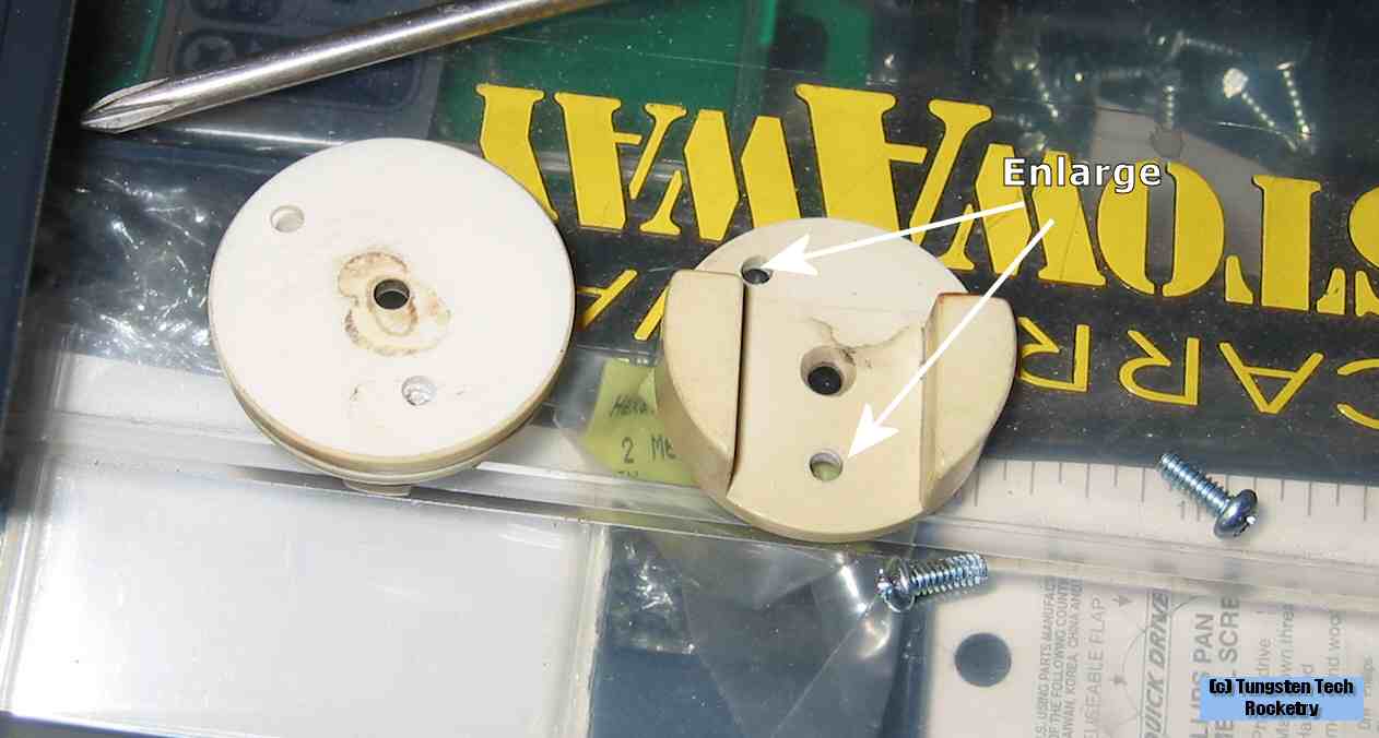
I then enlarged the holes on one side with the 1/8" drill so that the screw can turn freely in it. The screws are shown for reference.
Then it was time to glue and reassemble. Of course I cleaned and sanded the mating surfaces properly and then applied 15 minute epoxy. I carefully inserted the screws and tightened them, avoiding squeezing out all epoxy. Wipe with a rag or paper towel. I wear nitrile gloves when dealing with epoxy. I cured the construction at a warm spot, inside the microwave over actually. Now of course I didn't turn the oven on but it's a 'below the cabinet' model that has two lights in the bottom. These warm up the inside of the oven nicely.
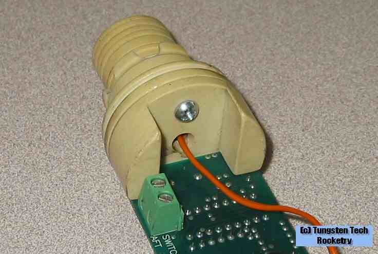
Unfortunately I forgot to take a picture of the end result but after launching a day or two later I took the following two pictures:
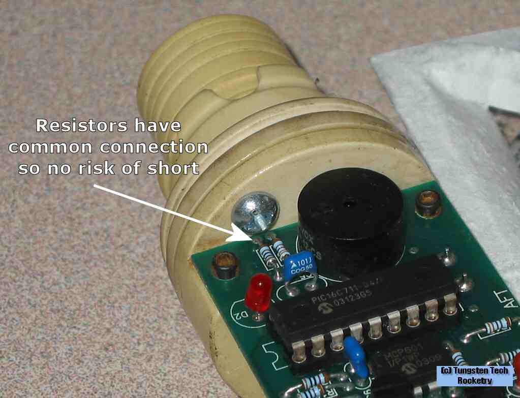
The two resistors are actually connected to a single circuit where the screw is. There is clearance but just in case if through some freak accident the screw shorted the two resistors nothing would happen.
That's it! Be sure to send me feedback if you have comments or questions!
All content is the responsibility of LUNAR.
If you have comments or suggestions regarding these web pages,
please contact the 
Copyright © 1992 - 2026 LUNAR