 LUNAR’clips
2001
Volume 8, Number 4
LUNAR’clips
2001
Volume 8, Number 4LUNAR’clips
2001
Volume 8, Number 4
Livermore Unit of the National Association of Rocketry July/December 2001
Copyright © 2001 by LUNAR, All rights reserved.
William J. Orvis, LUNAR#309
Last year, LUNAR had 18 launch pads in operation. We break the pads into three racks of six and operate each rack as a block. That is, racks one and three might be loading while rack two was being launched. We typically use racks one and two for low power (A through E engines) and rack three for high-power (F through H) launches. When the lines get long, we also open up rack three for low power launches. Racks one and two are 100 feet from the launch controller and rack three is 100 feet beyond rack one. Last year, all the racks were running at capacity at almost every launch.
As the lines got longer and longer, we decided that we needed another rack of 6 launch pads. Our original launch controller was already wired for up to 24 pads, but we had some new requirements for the new pads based on our experience with the existing ones:
The old launch system consists of the launch controller (Fig. 1), One 100 foot extension cord for each of the 12 low power pads and two 100 foot extension cords for each of the 6 high-power pads. At the pad end of the extension cords are interchangeable adapters with either alligator or copperhead clips.
Fig. 1, The existing LUNAR launch controller. This controller handles up to 24 launch pads in racks of 6. It has the capability to launch any combination of the 24 pads at one time.
If you add them up, you will see that our current system uses 24, 100 foot extension cords all of which must be stored in our equipment trailer. The current launch controller has sockets for 6 more pads but there is no room in the trailer for 12 more extension cords.
Figure 2 is the schematic of the original launch controller. It operates on either a 12 V power supply or battery. When power is applied to the system, a 20,000 mfd capacitor is charged to prevent voltage sags when a rocket is launched. There is a diode in the input circuit to prevent power with the wrong polarity from damaging the system. There is also a meter in the input circuit that can measure either the voltage or current flowing into the controller.
Fig. 2, The schematic of the existing LUNAR launch controller (Click the image for a larger view).
There is a safety foot switch that must be closed to supply power to the launch relays and to the continuity testing circuit. There is also a key switch in that circuit though we find that we rarely use it.
Pads are connected to the launch circuits through four banks of toggle switches, one bank for each rack of pads. The toggle switches are protected with a plastic block that cannot be placed over the switches unless all the switches in a bank are off. You can just make out the clear plastic blocks over the four banks of switches in figure 1.
When the launch control officer (LCO) steps on the safety switch, power is applied to the launch relays and to the continuity tester. Power is also applied to a relay that sits across the input diode to eliminate the diode loss in the circuit (about 1/2 Volt). This relay was added to the original design because it was thought that the 1/2 volt loss could be significant for igniters rated at 12 Volts.
The continuity tester sends a small amount of current through whichever pad or pads are enabled and emits a beeping sound if the continuity is good. A valid continuity check can only be done with a single pad is enabled. Otherwise, all you know is that at least one of the enabled pads has continuity.
The continuity checker consists primarily of a 6N139 High-Gain Optoisolator. This chip is extremely sensitive to very low currents so we limit the current to about half a milliamp with a 19.6 K ohm resistor. Flash bulb igniters are the most sensitive to current but are considered safe for currents less than 50 milliamps. Our circuit gives us a two order of magnitude (100) safety margin under this limit. The output side of the circuit is connected to an LED and a miniature buzzer to indicate when continuity is present.
When the launch button is pressed, the first launch relay closes which energizes the second relay which locks the first relay on. The relays stay locked on until the safety foot switch is released. We do this to prevent misfires caused by people letting go of the launch button too quickly.
All the relays have shorting diodes across their coils to absorb any high voltage transients caused by the relay being turned on or off quickly. There is also a zener diode across the pads to absorb any high voltage transients in that circuit. There are LEDs in the launch circuit to let you know if one of the launch relays has welded closed.
In operation, the Launch Control Officer closes one rack of pads for access. He then removes the plastic block protecting the pad enable switches for that rack, steps on the safety foot switch, and cycles all the pad enable switches to test the continuity of each pad in that rack. If a pad fails, he can reopen the pads and send the owner in to fix the problem. When all the pads have good continuity, the Launch Control Officer proceeds to enable one or more of the pads in the bank, does the countdown, and fires the rocket. The system has the capability to launch all 24 pads at the same time, creating a huge drag race though I don’t recall anyone ever trying that. The largest drag race I have seen was 9 Estes Mosquitoes and one Super Mosquito (mine). There’s a video of that launch on the LUNAR website.
The third requirement (fewer than 12 extension cords) for the new system caused the biggest change in how the system operates. The only way to do this is to have remote switching at the pads that is controlled by the launch controller. You can do this by having a single, multiconductor wire doing the selecting and two 100 foot extension cords to bring out the power. These store on three wire reels instead of the 12 needed for the old system, a significant savings in space.
The fifth requirement is that it must more reliably fire Copperhead igniters. A difficulty with firing any igniters at the end of a long extension cord is the fact that the resistance of the cord is about equal to the resistance in the igniter. The result is that only about half of the power in the launch controller actually reaches the igniter. This also means that the voltage across a Copperhead igniter is only 6 Volts instead of the specified 12 Volts.
To fix this problem, you need to either use bigger power cables or move the launch power out to the launch pads to shorten the distance between the power source and the igniter. I didn’t want to run battery cables 200 feet out to the pad, so I decided to move the power out to the pad. You have two options for doing this, batteries or a large capacitor at the pad. I originally considered putting a motorcycle battery or gellcell at the pads but there is a difficulty with that setup when you consider the safety issues. If the power at the pads is on all the time you need reliable sensors and locks to insure that a relay has not welded and is not still supplying power to one of the pads.
A better solution is to put a large capacitor at the pads, charge it when it is time to launch and discharge it before allowing people near the pads. In this way, there is no power at the pads and even if all the relays are welded a rocket cannot be launched. When I started looking for large capacitors, I couldn’t find any really big ones in the electronics supply catalogs because there is not much of a market for them there. I did find some huge ones for the uninterrupted power supply market but they were expensive and too sensitive to over voltages.
Warren Massey finally found one developed for car stereo market. In that market there is a need for large capacitors to prevent power sags when the big subwoofer on your car stereo kicks in. There he found 12 V,. 1 Farad (that’s not a mistype, it is a full Farad) capacitors for sale for a reasonable price ($60). There are even larger ones available (up to 2.5 farads) but my figures show that one farad should easily fire 6 or more copperheads without the voltage dropping below 11 volts. Actually, I was a little concerned that if the alligator clips were shorted, that much power might burn off the wires going to the pad. A quick test showed that was not a problem. I did find out that you can vaporize the aluminum leads that Estes puts on its igniters and you can spot weld a copper wire to the top of a capacitor just by touching it.
So, now I have a plan and it is compatible with the existing launch controller and does not require a significant amount of reconfiguration..
Figure 3 shows the electronic design of the new launch system. You will see a lot more complexity than the original system but if you look closely, you will see the old launch controller system hidden within the new system. Everything to the left of center in the new diagram is in the existing launch controller and everything to the right is in a rack control box out by the pads.
Fig. 3, Schematic of the new LUNAR launch system (click to see a larger image).
The new system does continuity testing using a separate wire from the one that launches the rockets, which necessitated adding a second continuity testing circuit. I also had to add another fire control relay for the same reason.
When the LCO is ready to launch a rack under the control of the new system, he must first remove the plastic switch cover. The plastic switch cover for the new rack has a shorted phone plug screwed to the back. The LCO inserts this plug into a phone jack above the pad enable switches. This phone jack is near the top center of figure 3 and energises the charge/discharge relay.
Originally, I was going to use a switched phone jack and let it carry the current for changing and discharging the capacitor. After melting the solder tabs off of a jack during a test, I realized that the phone jacks were not going to make it.
When the Charge/discharge relay closes, it starts changing the capacitor through a 10 ohm, 10 watt resistor. This resistor is to keep the charge/discharge currents under control. You could put a larger resistor here to reduce the current even more but that would cause a corresponding increase in the amount of time that it takes for the capacitor to charge or discharge. In an RC circuit, the time constant for charging or discharging is:
![]()
As it takes a capacitor about three time constants to be fully charged or discharged, this amounts to about 30 seconds to charge or discharge the capacitor. I can’t realistically make the charge/discharge time any longer than 30 seconds.
You could make the resistor smaller to speed up the charge/discharge time but that would significantly increase the current in the circuit, possibly damaging the wires or the capacitor. That is, using 10 ohms the instantaneous charging current at the instant you start charging or discharging the capacitor is,
![]()
which is not bad. However, if you decrease the resistance to 1 ohm, this suddenly jumps to 12 Amps which can do significant damage to small wires and connectors. It does get the capacitor charged in 3 seconds, but at the expense of a puff of smoke coming out of the launch controller. Oh yes, requirement number 6 is no smoke coming out of the equipment, only the rockets get to make smoke.
To the right of the 10 ohm resistor, you find two sets of LEDs. The first has a single LED and a 470 ohm ballast resistor. This led turns on as soon as the capacitor is charged to over 2 volts, meaning that it could launch a rocket. This is the danger LED, if this light is on, no one goes near the pads. The second set consists of 7 LEDs and a 470 ohm resistor. These LEDs turn on when the voltage is above 11 volts, indicating that the capacitor is essentially charged and you can start launching rockets. The number of LEDs was determined experimentally as different LEDs have different turn on voltages.
Below the LEDs is the new continuity circuit designed to test the continuity in the currently selected pad. Note that it uses a special "test" wire that is only connected to a pad when the pad is selected with one of the selection switches. The test circuit itself is identical to the one used for the lower 18 pads.
To the right of the continuity test circuit, are the pad enable switches. In the old section of the controller, these switches connect a pad directly to the launch relay. In the new section of the launch controller, each of these switches powers a wire that energizes a pad selection relay in the rack control box which connects a pad to the launch relay in the rack control box. When a pad selection relay is energized, the LCO can test the continuity in the selected pad by turning on the safety foot switch. If the LCO holds down the safety foot switch and presses the launch button, the launch relays again lock on, which energizes the launch relay in the rack control box, and discharges the capacitor through the igniters in the selected pads.
Above the pad enable relays are another set of continuity testers, one for each pad. These are available for continuity testing at the pad. Igniter failure is the most common form of launch failure we have. The circuit is exactly the same as that used by the LCO to test continuity.
Note the buzzer and LED next to the launch relay in the rack control box. The buzzer is very loud and it beeps, which causes the LED to flash. Whenever the capacitor is charged above 2 volts, this buzzer comes on to warn users that there is power in the rack control box and they should stay away.
As far as the user is concerned, the new launch controller works the same as the old one so the LCO does not get confused and make a mistake. The only difference is that we have given the LCO a convenient spot to store the plastic switch protector, which also energizes that rack.
Figure 4 shows the Rack Control Box. This is the box that is out by the pads that contains the 1 Farad capacitor, the pad select relays, and the launch relay. The large black cylinder is the 1 Farad capacitor. It sits on top of the relay box. Out of the relay box come six 20 foot power cords, one for each pad. About 18 inches from the end of each power cord is a remote continuity tester (the small silver box with a button on the top). All of this but the two wire reels in the foreground fit into an inexpensive plastic toolbox. Simply wind up the power cords from the pads, stuff them in the tool box, unplug the power and control cords, and you are ready to carry it away.
Fig. 4, The Rack Control Box. This box contains the 1 Farad capacitor, the pad select relays, and the launch relay. The box is also a handy place to store all the cables.
The power cords were made from 25 foot extension cords. Five feet were cut off the end of the cords that had the male plug and the power cords were wired into the relay box. The remaining five foot chunks were cut in half and used to make twelve adapters, six with alligator clips and six with Copperhead clips.
The two reels of cord in the foreground are the power cord on the left and the control cord on the right. There is a second power cord reel that is not shown in this figure. The power cords are made from 100 foot extension cords (16 ga, 3 wire) with the ends replaced with 4 wire trailer power connectors. While I could have used the 110 volt plugs and sockets that were already on the cable I felt that there was too much of a risk that someone would plug this box into a 110 Volt outlet. Putting 110 volts across the 1 Farad 12 volt capacitor would likely have an interesting effect as long as you were not close by when the effect happened.
Switching to 12 Volt connectors alleviated that problem. I did modify the 12 Volt trailer connectors slightly to fix them so that they could not be plugged in rotated 90 or 180 degrees out of normal. Even though there is a keyway to prevent plugging them in wrong, I found that there is enough play between the plug and the socket to allow it to be done. I modified the connectors by cutting one of the 4 pins (I only needed 3 anyway) and plugging the appropriate hole in the socket. With this modification, there is only one way that this cable can be plugged in.
The right hand cable is the control cable. All 200 feet of the control cable fits on the single reel. I made it out of stranded, cat 5 Ethernet cable. Cat 5 Ethernet cable contains eight wires as four twisted pair. Now, I don’t need high quality, twisted pair Ethernet cable for this application. Any flexible cable with eight wires in it works just fine. It turns out that with the amount of Cat 5 cable being installed these days that it is not difficult to find a better deal on it than on simple eight conductor cable.
I chose stranded cable because this cable is going to be unrolled and rolled at every launch and stranded cable holds up better in situations where it is going to be flexed. The cable is terminated in 8 pin DIN connectors though any good phased, 8 conductor connector would work. Be sure it is a phased connector so it can only be plugged in one way.
Figure 5 shows the Rack Control Box with the lid removed from the relay box. Inside you can see the six pad select relays, three on each side, and the launch relay at the bottom left near the fuse holder. I used automotive headlight relays because they are reliable, high current (30A) relays. They are also easy to replace as they simply plug into a socket instead of being soldered into the system.
Fig. 5, The Rack Control Box with the lid of the relay box removed.
Glued over a hole in the lid of the box is the warning buzzer and out of sight behind it is the warning LED. You can see the control cable plugging into the DIN-8 connector on the right and the power cable plugged into the silver trailer connector just to the right of the capacitor. The wiring looks like a mess, but just under it are five rows of component headers. Each color of wire goes to a single row of headers and the colors and wiring are drawn on the bottom of the box to help prevent mistakes.
Note the small plastic box that covers the two screw terminals on top of the capacitor. That box was made from the plastic box that screws come in by opening the lid and drilling two holes in the bottom that align with the two screw terminals on top of the capacitor. This box prevents the uninsulated terminals of the capacitor from shorting against a metal object in the box.
The launch controller was modified by removing the six 110 Volt receptacles that would have gone to the six pads and replace them with a DIN-8 connector and a trailer power connector. The switches were originally wired to the receptacles so all that wiring had to be removed. All the new circuitry was mounted on two circuit boards shown in figure 6. The boards were mounted into the controller and wired into the circuits.
Fig. 6, Layout of the circuit boards for modifying the launch controller.
Figure 7 shows one of the remote continuity testers with an alligator clip adapter. This tester hangs on the side of the launch pad where it is within easy reach of the rocketeer. Pushing the black button on the front of the box gives both an audible and visual indication of continuity.
Fig. 7 A remote continuity tester.
Figure 8 shows the box with the top removed. The circuit is in a junction box designed for a light switch, with a solid, screw on top. The orange extension cord is not cut, but is simply threaded through rubber grommets at each end of the box and clamped in place with a wire clamp. The insulation is then split so that wires can be soldered to the three wires in the extension cord without cutting or shorting them. A generous glob of ShoeGoo on the connections insures that there will not be any shorts. The box is sealed with ShoeGoo on the rubber grommets and a gasket designed for outdoor electric plugs around the top. The buzzer is attached over a hole in the bottom of the box using ShoeGoo.
Fig. 8, A remote continuity tester with the top removed.
Figure 9 shows the box with the circuit board disconnected from the lid of the box. All the electronics for the continuity tester are on the small circuit board. If you look closely, you can see the optoisolator circuit (the small, white integrated circuit), the push button switch, and the LED. The layout of this board is shown in figure 10. I actually used a 15K ohm plus a 10K ohm resistor to limit the current in the testing circuit instead of a single 19k ohm resistor as indicated in the diagram. The results are nearly the same.
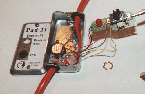
Fig. 9, The circuit board of the remote continuity tester.
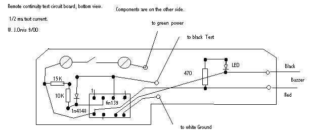
Fig 10, Layout of the circuit board of the remote continuity tester.
The circuit board is attached to the pushbutton switch by bending the screw terminals on the back of the switch out by 90 degrees and then screwing the circuit board to the switch using the screw terminals. The LED stands up on the circuit board next to the switch about as tall as the switch. The switch is then attached through a hole in the lid of the box with the LED pushed through another hole lined with a rubber grommet.
Pressing the button brings some power from the green wire in the extension cord, through a big resister, through the optoisolater circuit and to the black wire in the extension cord. The white wire in the extension cord is the ground. If the half milliamp can pass through the igniter from the black wire to the white wire, the optoisolater circuit detects it and sets off the light and buzzer.
That completes the electronic part of the pads, now lets look at the pads them selves. Anyone who has seen our pads will see an evolution in pad design as you look from our oldest pads (numbers 1 through 12) to these new ones. The oldest pads are all home made, with a home made tripod, and a homemade tilt and swivel. The next oldest pads (numbers 13 through 18) are less so, using a homemade tripod coupled with a Panavice for the tilt and swivel. For the new pads, I added a commercial folding tripod to the mix (see Fig. 11).
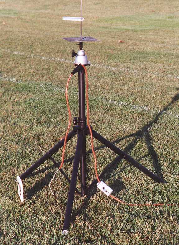
Fig. 11, The new LUNAR high-power launch pads.
The tripod is a heavy duty tripod designed for holding up speaker boxes at rock concerts. The tripods are made with lightweight black anodized aluminum tubing. The first step is to remove the whole top of the tripod including the adjusting screw, the mount for the speakers, and the inner tube that moves up and down for adjusting the height of the speakers. Get a plastic pipe fitting with threads on one side and a slip joint (the joint where you would glue to a plastic pipe) on the other that fits snugly on the tripod tube. Thread a pipe flange onto the threaded end of the fitting. Place the slip end of the fitting on the tripod tube. The fitting should fit snugly on the tripod tube. If not, shim it with tape. Drill three holes equally spaced around slip fitting, through it and through the aluminum tube. Attach the fitting to the tube with sheet metal screws.
The tripods are a bit top heavy when they have a 6 foot by one half inch diameter launch rod inserted in the top. To prevent the tripod from being knocked or blown over, we need to nail it to the ground. The bottom ends of the legs are not stiff enough to stand up to many weeks of pounding so we need to make some sort of an adapter that you can pound nails through. Remove the rubber feet that cover the bottoms of the three legs of the tripod. Find a piece of plastic pipe that is about 4 inches long and that just fits in the bottom end of the tripod tube. Glue a cap on the end of the pipe then drill a hole through the pipe cap that will just fit a large (6 to 8 inch) nail but not the head of the nail. Use tape around the pipe to get a snug fit in the tube then drill a small hole through the tube and pipe, and insert a sheet metal screw into the hole to lock the pipe in place. When the tripod is oriented the way you want it, simply pound a nail through the hole and into the ground to get a solid attachment to the ground. Another feature of these adapters is that they are easy to replace if an over zealous nail pounder manages to smash one.
The Panavices have three mounting holes spaced around the bottom of the vice. Unfortunately, the body of the Panavice is the same diameter as the pipe flange and the attachment holes stick outside the body. To attach the Panavice to the pipe flange, I slipped a bolt through each of the mounting holes, positioned the vice on top of the flange, and added a large washer and nut below the flange. When the nuts are tightened, the vice is clamped to the flange.
In figure 11, you can just see the Panavice (the silver thing with the ball on top), the black painted pipe flange just below it, and the black painted plastic pipe fitting screwed into the flange and attached to the top of the tripod.
Our launch rods have an adapter to make them all 3/8 inch in diameter at the bottom. In this way, all of our launch rods are interchangeable with all our launch pads. The 3/8 diameter is a legacy from our original set of launch pads. The clamp in the Panavice is designed for a 5/8 inch rod so we need an adapter to allow the standard launch rods to be used with the Panavice pads. The adapter can be seen in figure 11 between the Panavice and the flat blast deflector.
Warren Massey made the adapters and here is his description:
Cut a piece of 5/8 steel bar to a 4 inch length. In a lathe, square the cut ends and bore out the bar piece with the next-larger-than-3/8" "letter" (A-Z) drill. Cut a piece of 5/8" black pipe to a length of 2". Bore the pipe piece so it will slide over the bar piece. Take a large flat washer whose ID is slightly under 5/8" and whose OD is 1" or greater and bore out the ID so it will slide over the bar piece. On a smooth, level firebrick, place the flat washer down and stand the bar piece in the hole in the washer. Slide the pipe piece down over the bar piece until it contacts the flat washer. Braze (I used an oxy-acetylene torch, a mapp gas torch might work, a propane torch will not) the pipe piece to the bar piece and the washer piece. After it cools and the hardened brazing flux has been cleaned away, drill and tap a 10-24 hole radially through the combined walls of the pipe and bar pieces, 1 down from the washer. Clean and paint.
This adapter is clamped in the Panavice and a blast deflector (1/4 inch stainless steel plate with a 3/8 hole in it) is balanced on the washer end of the adapter. A launch rod is then inserted through the blast deflector into the 3/8 hole in the adapter. A thumbscrew in the side of the adapter locks the launch rod in place.
The launch rods are made from 304 stainless steel in diameters 1/8, 3/16, 1/4, 3/8, and 1/2 inches. The small diameter rods (1/8 inch) are 4 feet long while the larger ones are 6 feet long. While they are more expensive, the stainless steel rods hold up much better than plain steel when you consider the corrosive effects of rocket exhaust and moisture. We give them a good cleaning once a year and they look shiny like new. To adapt them to our standard 3/8 size, take a four inch piece of soft steel and drill down the center of one end a distance of about one inch. The drill diameter should be just slightly larger than the diameter of the launch rod. Drill and tap another hole horizontally through the bar about 1/2 inch down from the top and insert an Allen screw in that hole. Insert the launch rod and lock it in place with the Allen screw. Grind off any part of the Allen screw that protrudes out of the hole.
Last is the standoff to hold the rocket above the blast deflector. These new standoffs are much simpler than the old ones. The standoffs get burned up so often that I chose a design that is easy to make so I can simply replace damaged ones instead of trying to fix them. The standoff is a piece of 3/4 inch square aluminum channel stock (U shaped) about 6 inches long. Lay the piece of channel stock on its side and about one inch from the end, drill a slightly larger than 1/2 inch hole through both sides of the channel. Drill and tap a hole in the top of the channel that aligns with the center of the 1/2 inch hole for a 10-24 thumb screw. The 1/2 inch hole will slip over any of our launch rods and can be clamped in place using the thumb screw. The standoff can be seen sticking out sideways from the launch rod just above the blast deflector plate in figure 11.
The new pads are set up a little differently from our existing pads. Our existing pads are setup in a line facing the launch controller. The new pads are setup in an open sided circle with the Rack Control Box at the center and the open side facing the Launch Controller (See Figure 12). In figure 12, you can see all the launch equipment at the center of the circle, including the Rack Control Box and the launch rods. The launch rods are stored in a piece of 4 inch plastic pipe with plastic sewer cleanouts and plugs at each end (The white tube at the center of the figure).. To get to the rods, you simply unscrew the plastic plug.
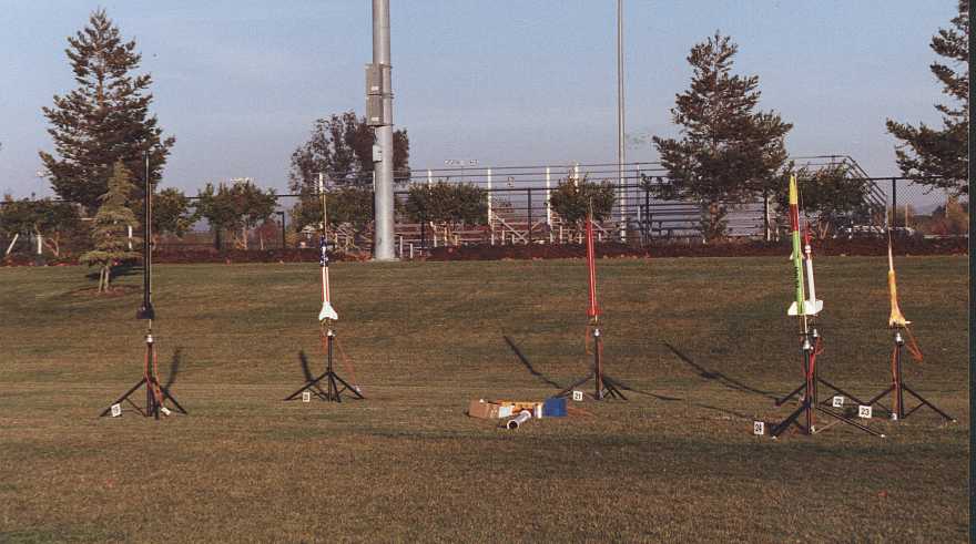
Fig. 12, The new pads ready for their first launch. The Rack Control Box is at the center of the circle and the launch pads are spread in a circle around it. The white tube is for transporting the launch rods.
Figure 12 shows the new launch pads loaded and ready for their first use. The Launch Control Officer enabled pad 19, tested continuity, did the count down, and pressed the launch button. There was a huge blast of sparks on the ground coming from the Remote Continuity Tester. I thought, "Oh Great!!!" (and a few other things). Even though I had tested the system many times in my garage, it looked like I had missed something and the launcher was going to try to launch the continuity testers instead of the rocket. I was about to stop the launch when I noticed something. Take a look at pad 19 (it is the one on the far left in figure 12). Notice that the wire goes up to the rocket and then comes back down. Apparently, the igniter had fallen out of the rocket just before we tried to launch it and was sitting next to the continuity tester. When we tried to fire the rocket, the system dutifully fired the igniter, which made a shower of sparks that only appeared to have come from the continuity tester.
I am much relieved and we progress with the second rocket in the rack, which makes a perfect launch (Fig. 13).
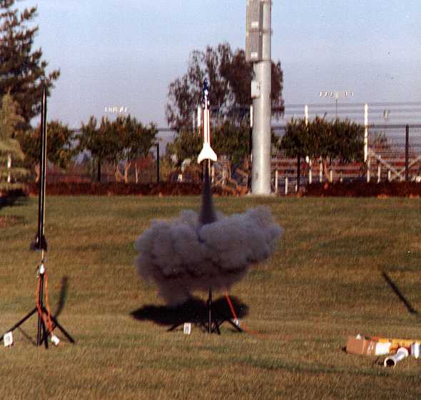
Fig. 13, The new LUNAR launch pads get off their first rocket.
Revised adapter description 10/24/06
Return to IndexAll content is the responsibility of LUNAR.
If you have comments or suggestions regarding these web pages,
please contact the 
Copyright © 1992 - 2026 LUNAR