 LUNAR’clips
LUNAR’clips
Livermore Unit of the National Association of Rocketry March/April 2002
Copyright © 2002 by LUNAR, All rights reserved.
I became interested in doing some rocketry electronics early in 1998 after discovering the Micro Chip PIC devices. For those that don't know, PIC devices are small, cheap, RISC based micro controllers. There are several families of these devices and they range in capacity from 8 pin devices with limited capabilities to 40 pin devices with built in ADC's, massive I/O, PCM, the works.
I test code for a living, and at that time I was working on an embedded system for a complex medical device (an ICD or Implanted Cardiac Defibrillator). Therefore, I was in the right frame of mind to start a new project.
However, I am not an EE, so I figured it would be a reasonable challenge for me to pull it all off. It was, but it was fun.
My intention was to provide a backup deployment device for my video rocket "Vidiot" since at least half of all HPR failures (at least mine, anyway) seem to be in the "failure to deploy" arena. Motor delay is almost always less than precise, and frequently totally unreliable, so an electronic backup seemed reasonable, especially since I was spending a whole bunch of bucks ($) on Vidiot. The reality was, however, that I did not finish the timer before I launched Vidiot, and I DID have a deployment problem, although it would not have been helped by this timer. (A motor delay problem, it was WAY too short, and the 'chute deployed about a second after burn-out at full forward speed on an I161.)
Here is the schematic of the circuit I designed and used:
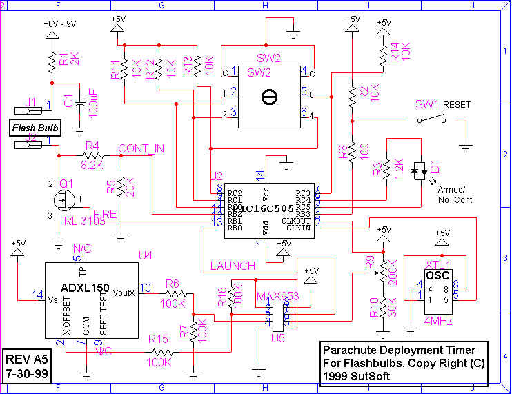
This circuit is designed to fire a standard AG1 flashbulb. It could be modified to fire an electric match, but would also require a minor code change.
I decided early on that there were several features I wanted in my timer. First, I wanted not to use burn wires, pull plugs or any other external mechanism for launch detection. I also wanted to use flashbulbs and not high current igniters. I wanted a reasonably large range of time. I also wanted to do some sort of continuity test that would not allow the timer to arm if it wasn't wired up correctly or had a bad flashbulb. I also wanted the time to be easy to set: none of this toggling of dip switches in a binary code to set the time.
I was able to design in all of the above criteria. For launch detection, I use an accelerometer chip made by Analog Devices, the ADXL150 single axis device. That satisfies the first objective. By using a very low On resistance FET (IRL3103) and a large capacitor in the firing circuit (100uF) the circuit will easily fire an AG1 flashbulb. Goal #2 covered. By using a micro, I can obtain a wide range of times and resolutions. That was goal #3. By using one of the micro's I/O lines I achieved the fourth goal. In addition, by using a hex encoded rotary switch, I achieved the final design goal.
The basic operation is quite simple. To use the timer, simply connect a flashbulb, set the required time by turning the rotary switch to the desired delay time (from 1 to 15 seconds) and press the reset button. That's all there is to it.
The LED reports status. If continuity is bad, it will flash RED/GREEN for six cycles, then the timer shuts off, and no further operation will occur. If the continuity is good, the LED will blink GREEN on and off for the same number of seconds as is set on the switch, one on/off cycle for each second selected. Then the LED goes RED indicating that it's armed and waiting for a launch detection.
Currently, launch detection is defined as 65ms of positive G-force, the exact amount determined by the setting of a pot. It is adjustable from zero to many G's. I have it set at about 4-5 G's currently, but less (~2 G's) is also reasonable. Because the detection is done in code, the setting time is fixed, but can be changed by changing the code.
A copy of the actual code I used is appended to this article. This is the latest version as of 7/2/2000. This version immediately goes to sleep when a battery is first installed. You must push the reset button once to wake it up and go through a continuity check/arming cycle.
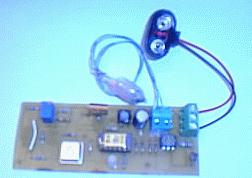
I have done a single sided PBC to use with this circuit. The board was done using TangoPCB for DOS, but I can provide a GIF or JPG file (basically just a scan) of the artwork, and you can etch your own board.
Most (if not all) of the parts can be ordered though Digikey via the web. I bought most of the small stuff at a local discount house (Halted Electronics) for less than $1. The FET, rotary switch, PIC micro and crystal oscillator are the high dollar parts and all of them can be found at Digikey. If you buy the one-time-programmable micro, they are only $2 each. The parts list is appended to this article.
I was also able to get both the accelerometer and the op-amp/comparator package as free samples from the manufacturers via their web pages. The ADXL150 costs about $15, but Analog Devices will give you two free if you ask for them. It's the same for the Maxim part.
If you are really serious about building one of these timers, please e-mail me and I can send you a ZIP file with all these documents complete. At some point, I expect to do a surface mount version of this device, mostly because I've never played with that and want to try. This version is much larger, but also much easier to assemble. But, for the hardy of spirit, (or those with surface mount experience) please check back here from time to time to see if I've got it done.
Here's a picture of the finished prototype. It's a little fuzzy but gives a good idea of what's up. The accelerometer is mounted on the back (trace side). The micro is in the middle (the gold colored part).
Good luck!
Some other helpful links:
Planet Microchip www.microchip.com
International Rectifier www.irf.com
Halted Electronics www.wco.com/~hsc/
Analog Devices (Free parts) www.analogdevices.com
Maxim Semiconductors (Free parts) www.maxim-ic.com
All content is the responsibility of LUNAR.
If you have comments or suggestions regarding these web pages,
please contact the 
Copyright © 1992 - 2026 LUNAR